Lithium Battery Charging - Lessons Learned
We installed lithium batteries and an inverter shortly after purchasing Karuna in 2022. Lithium has several advantages over lead acid batteries. A few advantages are, faster charging rates, ability to use a larger percentage of the battery, stable voltage curve, lighter weight.
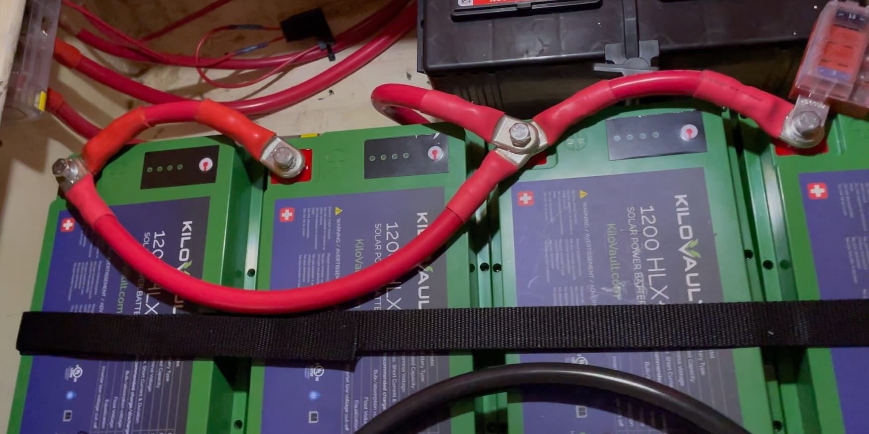
For our install we used the following major components.
- 4 x KiloVault HLX+ 100 Ah batteries
- MultiPlus-II 3kVa 120V Inverter/Charger
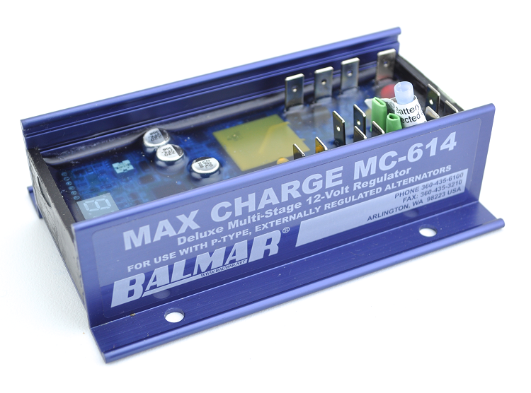
- Balmar MC-618 Alternator Voltage Regulator
- SmartSolar Charger – 300 watts solar
The install took a week or two of evenings. Everything seemed to work after the install, but it took some time to optimize the system.
During our first extended trip we noticed two issues. The battery would go into float after approximately 10 minutes. This prevented the battery from charging, especially when starting from a low state of charge. The second problem was when the battery was at float it would only maintain 70% state of charge.
These were both related to the stable voltage curve of lithium batteries. Most battery chargers only use voltage to determine the state of charge. This can be challenging with lithium batteries since the voltage is very stable.
| Voltage | State of Charge |
|---|---|
| 14.6V | 100% (Charging) |
| 13.6V | 100% (Resting) |
| 13.4V | 90% |
| 13.3V | 80% |
| 13.2V | 70% |
| 13.1V | 40% |
| 13.0V | 30% |
| 12.9V | 20% |
| 12.5V | 14% |
| 12.0V | 9% |
KiloVault’s charging settings are conservative since their focus is off-grid solar. I also wanted to be conservative since one of the risks when using lithium is the battery going offline due to over or under voltage.
Our initial charger settings were.
- Bulk Voltage – 14.1
- Absorption Voltage – 14.0
- Float Voltage – 13.4
Based on the voltage chart above a float voltage of 13.4 would only maintain the batteries at 90%. During our first extended trip we found the battery would only charge to approximately 70% with our initial settings. I suspect this was due to loads on the system plus our voltage sense wasn’t as accurate as it could be.
After two seasons we have modified the charger settings to the following. These settings have worked well and allow the state of charge to be maintained at over 95% when the battery is charged.
Alternator and Solar
- Bulk/Absorption voltage – 14.2V
- Float voltage – 13.5V
Shore Charger
- Bulk/Absorption voltage – 14.2V
- Float – 13.45V - This charges the battery to 90% - 95%.
- Float offseason – 13.35V - This allows the battery to drift to 70% - 80% when not in use.
Since the voltage curve is very flat accurate voltage sense is critical.
During our first extended trip when starting at a low state of charge, usually after anchoring, our alternator wouldn’t charge the battery properly. It would go from bulk into float after a few minutes.
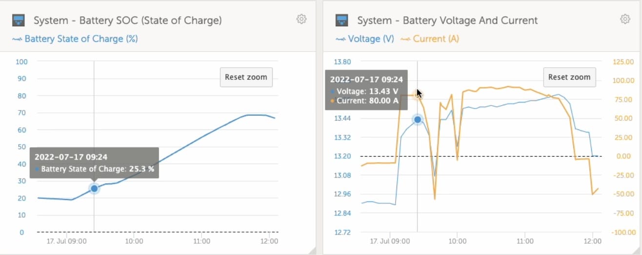
In the graph below the cursor is on point where the alternator went from bulk to float. The state of charge was only 25% and battery voltage 13.4V. This happened one more time when I verified the charging settings. Going into the programming menu starts the charging cycle over. As a workaround I set the minimum bulk duration to 90 minutes. This is the third charging cycle where the battery reached 70%.
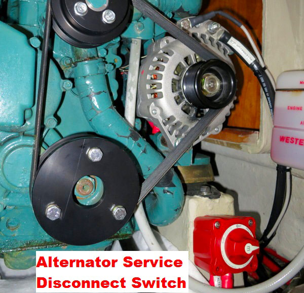
Our alternator voltage regulator, a Balmar MC-618, has a dedicated positive voltage sense, which I ran directly to the battery positive. There is no dedicated negative voltage sense.
From the Balmar Manual.
The BLACK Ground Wire #1 in diagram at right is included in the four-wire Ford-style plug on the wiring harness and is factory installed on regulator packages designated with “H” at the end of the model number. The other end of the Ground Wire is fitted with a ring terminal connector. In some applications, this wire can be connected directly to the alternator’s ground terminal post. For best accuracy ground as close to the battery as possible, especially when charging lithium batteries.
I missed the note at the end stating to run the ground as close to the battery as possible. In our first extended trip the negative was wired to the alternator. This was the configuration with the previous Balmar voltage regulator.
As stated above this mistake prevented the battery from charging properly. It would only bulk charge for a few minutes before going into float. I later determined this was due to the voltage drop across the negative wire at high charging currents.
Below shows the charging current, battery voltage, and voltage at the alternator.
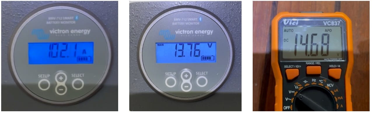
There is almost a full volt drop when charging at 100 amps. The negative voltage sense connected to the alternator caused the voltage regulator to sense .5 volts higher than the actual battery voltage. When the alternator voltage regulator thought it hit bulk voltage of 14.2 the battery voltage was only 13.7.
Moving the negative to the battery, pin 1 on the Balmar, allowed the alternator to properly charge the battery to near 100%.
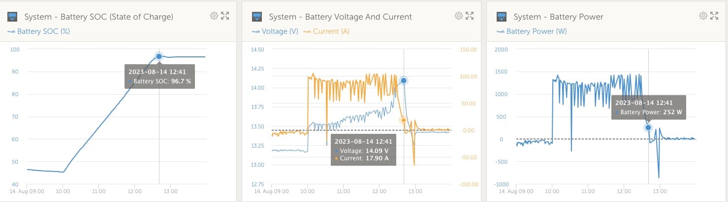
Our Victron devices, inverter and solar charger, use the shunt to sense voltage. We use a Victron BMV-712 Smart battery monitor, and it’s included shunt. We also use a Victron Cerbo GX which allows the Victron equipment to communicate with each other. We didn’t have the same charging issues with the Inverter/Charger.
Two excellent articles from Marine How To that I used to program and also troubleshoot.
A video I put together showing the challenges described in this post.